Top 5 Methods for Synthesizing Graphene Sheets: A Comparative Guide
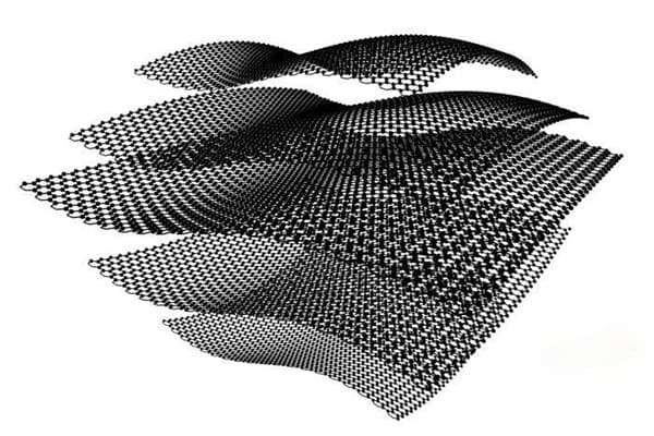
Graphene, a single layer of carbon atoms arranged in a two-dimensional honeycomb lattice, has gained immense attention for its exceptional properties, such as extraordinary electrical conductivity, mechanical strength, and thermal conductivity. These characteristics make it highly valuable in applications ranging from electronics and energy storage to biomedicine and sensors.
In order to harness the potential of graphene, it is essential to develop efficient and scalable methods for synthesizing high-quality graphene sheets. Various techniques have been developed to produce graphene, each with its advantages and limitations. This article will explore the top 5 methods for synthesizing graphene sheets, comparing their effectiveness based on factors such as cost, scalability, and quality.
At Advanced Ceramics Hub, we specialize in high-quality graphite material products with various forms and specifications, ensuring optimal performance for industrial and scientific applications.
Background on Graphene and Synthesis Challenges
Graphene’s structure—a two-dimensional sheet of sp²-bonded carbon atoms arranged in a honeycomb lattice—underpins its remarkable properties. Its high electron mobility (~200,000 cm²/V·s), thermal conductivity (~5000 W/m·K), and mechanical strength (~130 GPa tensile strength) make it a game-changer for applications ranging from transparent conductive films to high-capacity batteries. However, producing graphene that retains these properties at scale is fraught with challenges. High-quality graphene, with minimal defects and large sheet sizes, is essential for electronics, but achieving this often comes at the cost of low yield or high expense. Conversely, scalable methods may produce graphene with defects, such as vacancies or functional groups, that compromise performance.
The synthesis challenges include:
- Scalability: Producing large quantities of graphene for industrial applications.
- Quality Control: Minimizing defects like tears, wrinkles, or impurities.
- Cost: Balancing production costs with market demands for affordability.
- Environmental Impact: Reducing energy consumption and chemical waste.
These challenges necessitate a variety of synthesis methods, each tailored to specific needs. For example, laboratory research may prioritize pristine graphene, while industrial applications may favor cost-effective production. Understanding these trade-offs is crucial for selecting the right method, setting the stage for our exploration of the top five techniques.
Looking for top-quality graphite products? Explore Advanced Ceramics Hub’s selection.
Chemical Vapor Deposition (CVD)
Chemical vapor deposition (CVD) is one of the most widely used and reliable methods for producing high-quality graphene sheets. In this process, a carbon-containing gas, such as methane (CH₄), is introduced into a chamber at high temperatures (typically between 900–1000°C) in the presence of a metal catalyst (often copper or nickel). The carbon atoms decompose from the gas and arrange themselves into a single layer of graphene on the substrate.
1. Standard CVD Process
Key Steps
✅ Substrate Preparation
- Copper (Cu) or nickel (Ni) foils (most common)
- Surface cleaning (electropolishing, annealing at 1000°C in H₂/Ar)
✅ Gas Phase Reaction
- Precursor: Methane (CH₄), ethylene (C₂H₄), or acetylene (C₂H₂)
- Carrier Gas: Hydrogen (H₂) + argon (Ar)
✅ Typical Conditions:
- Temperature: 900–1050°C
- Pressure: Low (≤100 mTorr) or atmospheric
- Growth Time: 5–60 minutes
✅ Cooling & Transfer
- Controlled cooling rate (~10°C/min) to prevent wrinkles
- PMMA-assisted wet transfer or roll-to-roll techniques
Mechanism
- On Cu: Surface-mediated growth (self-limiting monolayer)
- On Ni: Carbon segregation/precipitation (multi-layer risk)
2. Advantages of CVD
- High Quality: The graphene produced by CVD is typically of high quality, with fewer defects and a uniform structure.
- Large Area Production: CVD allows for the creation of large-area graphene sheets, making it suitable for industrial applications.
- Versatility: CVD can be adapted to produce graphene on various substrates, including metals, silicon, and polymers.
3. CVD Variations & Innovations
| Method | Advantages | Limitations |
| Plasma-Enhanced (PE-CVD) | Lower temps (400–600°C) | Higher defects (sp³ hybridization) |
| Roll-to-Roll (R2R-CVD) | Continuous production (up to 30 m/h) | Requires flexible metal substrates |
| Laser-Assisted CVD | Localized growth, no substrate heating | Limited to small-area patterning |
| Cold-Wall CVD | Energy-efficient, fast heating/cooling | Temperature gradients cause non-uniformity |
4. Quality Control Metrics
| Parameter | Ideal Value | Typical Industrial Result |
| Defect Density | <0.1% (ID/IG ratio <0.1) | 0.5–2% (ID/IG ~0.3–1.0) |
| Sheet Resistance | <200 Ω/sq (monolayer) | 300–1000 Ω/sq |
| Uniformity | >95% coverage | 80–90% (edge effects remain) |
4. Applications by CVD Graphene Grade
| Quality Tier | Defect Level | Best Uses |
| Research-grade | <0.1% defects | Quantum devices, sensors |
| Industrial-grade | 0.5–1% | Flexible electronics, coatings |
| Bulk-grade | 1–3% | Composites, conductive inks |
Exploring our optimized graphite products.
Mechanical Exfoliation
Mechanical exfoliation, also known as the “Scotch tape method,” involves peeling thin layers of graphite using adhesive tape. The tape is pressed onto a piece of graphite and then pulled off, transferring thin graphene sheets onto a silicon wafer or other substrates. This method was famously used in the discovery of graphene.
1. Standard Exfoliation Process
✅ Source Material Preparation
- Highly ordered pyrolytic graphite (HOPG) or natural graphite flakes
- Clean surface (e.g., oxygen plasma treatment)
✅ Adhesive-Based Exfoliation
- Press and peel Scotch tape (or PDMS stamps) against the graphite
- Repeat folding/unfolding to thin down layers
✅ Substrate Transfer
- Press tape onto SiO₂/Si wafer (90-300 nm oxide layer optimal for visibility)
- Dissolve adhesive (acetone for tape, heat for PDMS)
✅ Identification & Characterization
- Optical microscopy (contrast difference for 1-5 layers)
- Raman spectroscopy (2D/G peak ratio confirms monolayer)
2. Key Advantages
✅ Ultra-high quality (lowest defects of any method, D peak often absent)
✅ No chemical contamination (unlike CVD or liquid-phase exfoliation)
✅ Immediate usability (no post-processing required)
3. Limitations & Challenges
| Issue | Impact | Workarounds |
| Low yield | <1% monolayers per exfoliation | Automated systems (see Section 5) |
| Small flake size | Typically 10-100 µm (max ~1 mm) | Deterministic transfer stacking |
| Non-scalable | Manual process; µg quantities per day | Reserved for fundamental research |
| Thickness control | Random layer number distribution | AFM pre-screening |
4. Scientific Applications
Despite its impracticality for industry, mechanical exfoliation is critical for:
- Quantum transport studies (ballistic electrons require defect-free lattices)
- 2D heterostructure assembly (manual pick-up of exfoliated flakes)
- Benchmarking (sets the standard for mobility >200,000 cm²/V·s)
Request a custom quote for high-quality graphite products.
Liquid-Phase Exfoliation (LPE)
Liquid-phase exfoliation (LPE) is a solution-based method for producing graphene and other 2D materials in bulk quantities. Unlike mechanical exfoliation (high quality but low yield) or CVD (high purity but complex setup), LPE offers a balance between scalability, cost, and tunable quality.
In liquid-phase exfoliation, graphite is dispersed in a liquid medium (usually water or organic solvent), and ultrasonic waves are applied to break the graphite into graphene sheets. This method is scalable and can be used for large quantities of graphene production.
1. Standard LPE Process
✅ Graphite Dispersion
- Source: Natural graphite, graphite oxide, or expanded graphite
- Solvent: NMP, DMF, water/surfactants (e.g., SDBS), or ionic liquids
✅ Exfoliation
Ultrasonication (bath or probe)
- Energy: 100–500 W, 1–24 hrs
- Yields: 0.1–5 mg/mL
Shear Mixing (high-speed rotor-stator)
- Scalable to liters/hour
✅ Purification & Separation
- Centrifugation (1000–10,000 rpm) to remove unexfoliated graphite
- Size selection: Gradient ultracentrifugation for monolayer enrichment
2. Advantages of LPE
✅ Scalability – Grams to kilograms per day
✅ Low cost – No high-temperature/vacuum equipment needed
✅ Versatility – Works with graphite, h-BN, MoS₂, etc.
✅ Solution-processable – Enables inks, coatings, and composites
3. Challenges & Limitations
| Issue | Impact | Solutions |
| Defects & Oxidation | sp³ defects from sonication (~5–20%) | Mild solvents (NMP), short sonication |
| Thickness Control | Polydisperse flakes (1–10 layers) | Density gradient centrifugation |
| Low Concentration | Typically <5 mg/mL | Solvent optimization |
| Residual Surfactants | Can degrade electronic properties | Solvent exchange/annealing |
4. Industrial Applications
- Conductive Inks (Printed electronics, RFID tags)
- Coatings (Anti-corrosion, EMI shielding)
- Composites (Polymer reinforcement, batteries)
- Energy Storage (Supercapacitors, Li-ion anodes)
Chemical Reduction of Graphene Oxide
Graphene oxide (GO) can be chemically reduced to graphene by using reducing agents such as hydrazine, sodium borohydride, or ascorbic acid. This method is widely used to produce graphene from graphene oxide, which is easier to handle and disperse in solution compared to pure graphene.
Chemical reduction of graphene oxide (GO) is one of the most widely used methods for mass-producing reduced graphene oxide (rGO). This solution-based approach offers a balance between scalability, cost-effectiveness, and tunable material properties.
1. Standard Chemical Reduction Process
✅ Graphene Oxide Synthesis
- Typically via modified Hummers’ method (KMnO₄/H₂SO₄ oxidation of graphite)
- Results in heavily oxygenated (20-40 wt% oxygen), water-dispersible sheets
✅ Reduction Process
Common reducing agents:
- Hydrazine hydrate (N₂H₄) – Most effective but toxic
- Ascorbic acid – Green alternative
- HI/AcOH – Produces highly conductive rGO
- Thermal (200-1000°C) – No chemical reductants needed
✅ Post-Processing
- Washing to remove residual reagents
- Optional annealing to improve conductivity
- Functionalization (e.g., nitrogen doping)
2. Advantages of Chemical Reduction Method
✅ Scalability – Can produce grams to kilograms per batch
✅ Solution-processable – Enables coatings, composites, and inks
✅ Tunable properties – Reduction degree controls conductivity/hydrophobicity
✅ Low-cost – Uses inexpensive graphite precursor
3. Limitations and Challenges of Chemical Reduction Method
❌ Residual defects – sp³ carbon and oxygen groups remain
❌ Lower conductivity – Typically 1-2 orders below CVD graphene
❌ Aggregation – π-π stacking causes restacking of sheets
❌ Toxicity – Strong reductants like hydrazine are hazardous
4. Key Applications of Chemical Reduction Method
- Conductive composites (polymers, ceramics)
- Energy storage (battery anodes, supercapacitors)
- Sensors (gas, biosensors)
- Coatings (anti-corrosion, conductive)
Electrochemical Exfoliation
1. Standard Electrochemical Exfoliation Process
✅ Electrode Setup
- Anode: Graphite rod/flake
- Cathode: Pt wire or another graphite electrode
- Electrolyte: Aqueous (e.g., (NH₄)₂SO₄, H₂SO₄) – Produces oxidized graphene, or Organic (e.g., (C₂H₅)₄NBF₄ in propylene carbonate) – Yields low-defect graphene
✅ Voltage Application
- Low-voltage (1–5 V): Gentle intercalation and exfoliation
- High-voltage (>5 V): Faster but introduces more defects
✅ Exfoliation & Collection
- Gas evolution (O₂, H₂, SO₂) helps separate graphene layers
- Centrifugation removes unexfoliated graphite
✅ Post-Processing (Optional)
- Reduction: Thermal/chemical to restore conductivity
- Functionalization: Doping (N, S) or decoration (Ag, Au NPs)
2. Advantages of Electrochemical Exfoliation
✅ Scalable – Grams to kilograms per day
✅ Tunable oxidation – From pristine to GO-like graphene
✅ Low-cost – No high-temperature or vacuum equipment
✅ Fast – Exfoliation completes in minutes to hours
3. Challenges & Limitations
| Issue | Impact | Solutions |
| Defect introduction | Over-oxidation at high voltages | Optimize voltage (<3 V for minimal defects) |
| Flake size control | Depends on the graphite source | Pre-treat graphite (e.g., expand) |
| Residual salts | Can degrade electronic properties | Dialysis or repeated washing |
| Yield variability | Depends on graphite source | Use highly ordered graphite (HOPG) |
4. Industrial Applications
- Conductive inks & coatings (flexible electronics)
- Energy storage (Li-ion batteries, supercapacitors)
- Sensors (electrochemical biosensors)
- Polymer composites (mechanical reinforcement)
At Advanced Ceramics Hub, we supply optimized-grade ceramic products that comply with ASTM and ISO standards, ensuring outstanding quality and reliability.
Comparison of Graphene Sheet Synthesis Methods
Explore key methods—mechanical exfoliation, CVD, liquid-phase exfoliation, chemical reduction of GO, and electrochemical exfoliation—with critical metrics on quality, cost, and applications to optimize your material choice.
1. Quality & Structural Properties
| Method | Layer Control | Defect Density (ID/IG) | C/O Ratio | Flake Size |
| Mechanical Exfoliation | Excellent (1-3 L) | <0.1 | >50:1 | 10-1000 μm |
| CVD | Good (1-5 L) | 0.1-1.0 | >30:1 | Unlimited* |
| Liquid-Phase Exfoliation | Moderate (1-10 L) | 0.5-2.0 | 8:1-12:1 | 0.1-5 μm |
| Chemical Reduction of GO | Poor (1-20 L) | 1.0-3.0 | 8:1-12:1 | 0.5-20 μm |
| Electrochemical Exfol. | Good (1-5 L) | 0.2-1.5 | 10:1-20:1 | 1-10 μm |
2. Scalability & Cost
| Method | Throughput | Cost (per gram) | Energy Intensity | Commercial Readiness |
| Mechanical Exfoliation | μg-day | $10,000+ | Low | Lab-only |
| CVD | g-hour (batch) | $50-500 | High | Industrial (electronics) |
| Liquid-Phase Exfoliation | g-day | $10-100 | Medium | Industrial (composites) |
| Chemical Reduction of GO | kg-day | $1-10 | Low | Mature production |
| Electrochemical Exfol. | g-hour | $5-50 | Medium | Emerging commercial |
3. Electronic Performance
| Method | Mobility (cm²/V·s) | Sheet Resistance (Ω/sq) | Best Electronic Application |
| Mechanical Exfoliation | 200,000 | 30-100 | Quantum devices |
| CVD | 10,000-50,000 | 100-300 | Flexible electronics |
| Liquid-Phase Exfoliation | 100-1,000 | 1,000-10,000 | Conductive composites |
| Chemical Reduction of GO | 1-100 | 1,000-100,000 | Sensors, coatings |
| Electrochemical Exfol. | 500-5,000 | 300-3,000 | Battery electrodes |
4. Industrial Applications
| Method | Primary Applications | Limitations for Industry |
| Mechanical Exfoliation | Fundamental research, prototype devices | Zero scalability |
| CVD | Transparent electrodes, semiconductor devices | High equipment costs |
| Liquid-Phase Exfoliation | Conductive inks, polymer composites | Residual solvent/surfactant issues |
| Chemical Reduction of GO | Energy storage, anti-corrosion coatings | High defect density |
| Electrochemical Exfol. | Printed electronics, supercapacitors | Batch-to-batch variability |
5. Environmental Impact
| Method | Hazardous Chemicals | Energy Consumption | Green Alternatives Available |
| Mechanical Exfoliation | None | Very Low | Yes (PDMS instead of tape) |
| CVD | CH₄/H₂ gases | Very High | No |
| Liquid-Phase Exfoliation | Organic solvents | Medium | Yes (water-based) |
| Chemical Reduction of GO | Strong oxidizers | Low | Yes (vitamin C reduction) |
| Electrochemical Exfol. | Acid electrolytes | Medium | Yes (neutral pH methods) |
Decision Guide: Which Method to Choose?
- For fundamental research → Mechanical exfoliation
- For electronics → CVD (if budget allows) or electrochemical
- For composites/coatings → Liquid-phase exfoliation
- For bulk production → Chemical reduction of GO
- For energy storage → Electrochemical exfoliation
Each method for synthesizing graphene sheets has its strengths and weaknesses. The best method depends on the specific application and requirements. For high-quality, large-area graphene, CVD is often the best choice, though it comes with high costs. For small-scale, high-quality research, mechanical exfoliation is ideal. Liquid-phase exfoliation is the most scalable method, making it suitable for large-scale production, while chemical reduction of graphene oxide offers a simple, cost-effective solution for large quantities of graphene at the expense of some quality. Electrochemical exfoliation is an emerging method that is both cost-effective and scalable, though it currently produces lower-quality graphene.
In conclusion, the choice of graphene synthesis method should be made based on the specific needs of the project, balancing cost, quality, and scalability. As research and technology progress, improvements in these methods will likely make graphene more accessible for a wider range of applications.
For top-quality advanced graphite ceramic materials, Advanced Ceramics Hub provides tailored solutions for various applications.
Looking for premium graphite ceramic materials? Contact us today!